Switch's Boot Process
Boot process of a switch involves several steps that allows switch to initialize and become operational. The specific steps can varies between different models of switches or vendors but the basic steps are usually similar across most switches. This blogpost will demonstrate boot process of a Cisco Catalyst 2960 switch. Boot process helps troubleshoot hardware issues on a switch sometimes we can also use this process to recover a forgotten password to access the device.
Boot Loader
The boot loader is a program responsible for booting a switch. It runs boot sequence process after switch is powered on.
The boot loader finds the Cisco IOS image on the switch by first looking in a directory that has the same name as the image file (excluding the .bin extension). If boot loader does not find the operating system software image, boot loader software searches each subdirectory before continuing the search in the original directory.
The operating system then initializes the interfaces using Cisco IOS commands found in the operating system configuration file, config.text, stored in the switch flash memory.
The boot loader commands support initializing flash, formatting flash, install a new IOS, changing the BOOT environment variable and recovery of a lost or forgotten passwords.
Switch’s Boot Sequence
A cisco switch goes through five-step boot sequence process after it is powered on:
Switch loads a power-on self-test (POST) program stored in ROM. POST checks the CPU subsystem. It tests the CPU, DRAM, and the portion of the flash device that makes up the flash file system.
POST: Power-On Self-test refers to the routines that run after a computer system is powered on. These routines are designed to check system resources and identify common hardware errors before the operating system loads.
Next, the switch loads the boot loader software. The boot loader is a small program stored in ROM and is run immediately after POST successfully completes.
The boot loader performs low-level CPU initialization. It initializes the CPU registers that control where physical memory is mapped, the quantity of memory, and memory speed.
CPU Registers: A register is a small, fast storage location within the CPU used to hold data temporarily during processing.
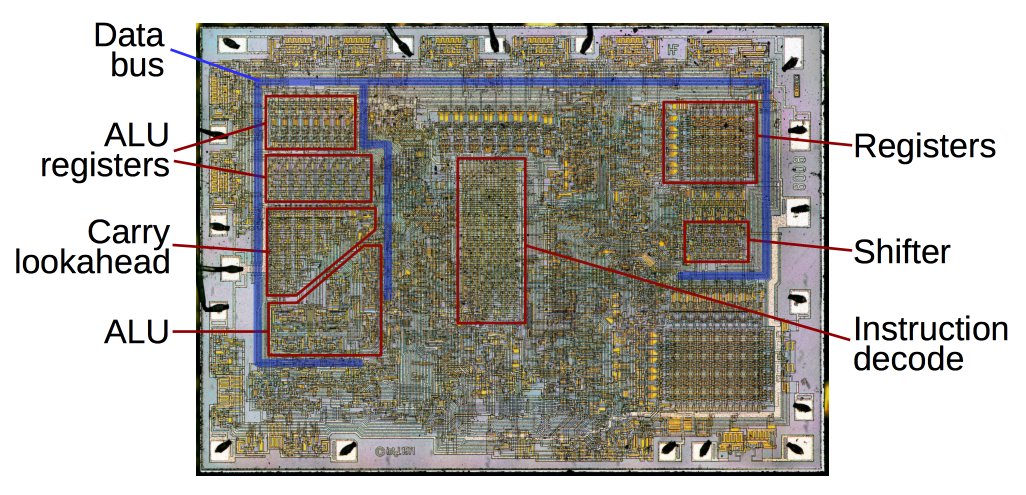
Image shows registers on a CPU as well as other components that makes up a CPU.
- The boot loader initializes the flash file system on the system board.
System board: Generally referred as motherboard or PCB (printed circuit board). It connects and allows communications between all the major components of the system - CPU, RAM, Storage, Graphic cards, input/output ports and other peripherals.
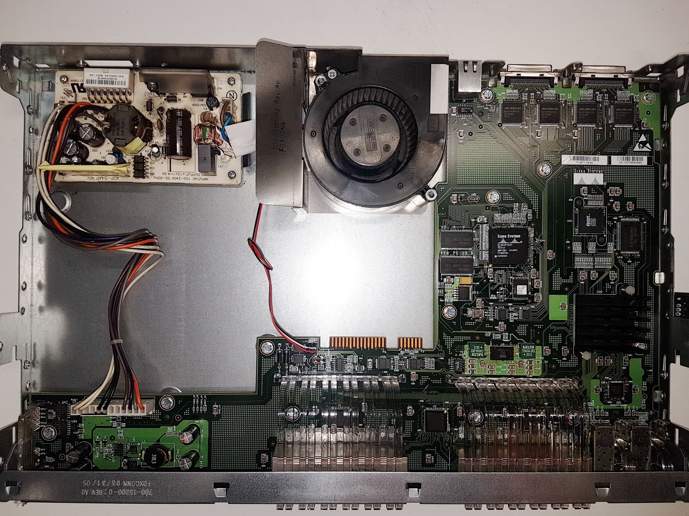
Cisco switch’s PCB shown in this picture.
- Finally, the boot loader locates and loads a default IOS operating system software image into memory and hands control of the switch over to the IOS.
The boot system Command
All switches comes with a default image in its flash memory. Often network teams tests the different versions of switch image and decided to use the the image they find is most reliable. Then the image is upload to switch and let switch to use the specified image version when it boots up.
BOOT environment variable is set using the boot system global configuration mode command.
The show boot command shows what the current IOS boot file is set to.
1
2
3
4
5
6
7
8
9
10
S1#show boot
BOOT path-list      : flash:c2960-lanbasek9-mz.122-50.SE4/c2960-lanbasek9-mz.122-50.SE4.bin
Config file         : flash:/config.text
Private Config file : flash:/private-config.text
Enable Break        : no
Manual Boot         : no
HELPER path-list    :
Auto upgrade        : yes
Auto upgrade path   :
NVRAM/Config file
1
S1(config)# boot system flash:/c2960-lanbasek9-mz.150-2.SE/c2960-lanbasek9-mz.150-2.SE.bin
| Command | Definition |
|---|---|
| boot system | The main command |
| flash: | The storage device |
| c2960-lanbasek9-mz.150-2.SE | The path to the file system |
| c2960-lanbasek9-mz.150-2.SE.bin | The IOS file name |
LED Indicators on Switch
Switch LED indicators are useful when we are physically inspecting switch status. The following figure shows eight LED indicators on a Cisco Catalyst 2960 switch.
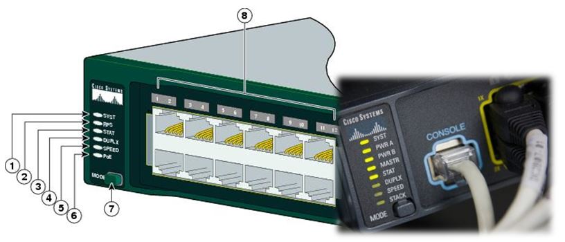
Note: Marking number 7 is pointing to the mode button, mode button needs to be pressed to cycle through LED modes from number 1 to 6. Marking number 8 indicates to the ports numbers, an LED close to switch port can be reelects there.
SYST: System LED represents the system power, whether switch is receiving power or not and it’s proper functionality. An Amber LED means switch is receiving power but is not functioning properly.
RPS: Redundant Power System, if the main power supply fails, the RPS automatically takes over to prevent downtime.
LED Light Definition Solid green Providing backup power Blinking green RPS connected but unavailable as it’s providing power to another device No Light RPS is not connected Solid amber RPS is in standby mode or in a fault condition. Blinking amber Internal power supply is the switch has failed, and RPS is providing power. STAT: Port Status LED, This LED helps determining the switch port status. Switches usually have STAT mode selected by default thus we see blinking lights on switch’s ports. We can select the mode manually by pressing MODE button.
LED Light Definition No LED No Link Solid Green Link is present Blinking Green Link has activity, port is receiving and sending data Alternating Green-Amber Link has fault Solid Amber Port is blocked to ensure a loop doesn’t exist, stays amber for 30 seconds after it is activated Blinking Amber Port is blocked to prevent loop in the forwarding domain DUPLX: Port Duplex LED, LED’s that are off in half-duplex mode. If the port LED is green, the port is in full-duplex mode.
SPEED: Port Speed LED, Shows the port speeds with different LED status.
LED Light Definition LED is off Port is operating at 10 Mbps LED is Solid Green Port is operating at 100 Mbps LED is blinking Green Port is operating at 1000 Mbps PoE: Power over Ethernet (POE) Mode LED, if the PoE is supported on switch port, a PoE mode LED will present. There is a LED on mode and LED on ports as well referred in marking 7 and 8.
LED Light Definition LED is off PoE is off LED is blinking amber PoE mode is not selected but at least one of the ports has been denied power or has PoE fault LED is green PoE mode is selected and the port LEDs will display colors with different meanings. Port LED is off PoE is off Port LED is solid green PoE is on Port LED is alternating green-amber PoE is denied because providing power to the powered device will exceed the switch power capacity. LED is amber Port PoE is disabled
Recovering from system crash
Recovering from a System Crash, if the operating system or system files on a Cisco switch are missing, corrupted, or damaged the switch typically enter into bootloader mode also referred as ROMmon mode instead of booting into the normal operating system.
A console cable is required to access boot loader. The following explains the process:
Connect a PC by console cable to the switch console port. Configure terminal emulation software like Putty to connect to the switch.
Disconnect the switch power cord.
Plug the power cord to switch and within 15 seconds, press and hold the Mode button while the System LED is still flashing green.
Continue pressing the Mode button until the System LED turns briefly amber and ten solid green; then release the Mode button.
The boot loader switch: prompt appears in the terminal emulation software on the PC.
Note: Switch interface mode will show switch:, the colon represents switch in it’s bootloader mode.
1
2
switch: set
BOOT=flash:/c2960-lanbasek9-mz.122-55.SE7/c2960-lanbasek9-mz.122-55.SE7.bin
set command appears in the terminal emulation software on the PC.
flash_init command to view the current files in flash.
1
2
3
4
5
6
7
8
9
switch: flash_init
    Initializing Flash...
    flashfs[0]: 2 files, 1 directories
    flashfs[0]: 0 orphaned files, 0 orphaned directories
    flashfs[0]: Total bytes: 32514048
    flashfs[0]: Bytes used: 11838464
    flashfs[0]: Bytes available: 20675584
    flashfs[0]: flashfs fsck took 10 seconds.
    ...done Initializing Flash.
dir flash: command to view the directories and files in the flash.
1
2
3
4
5
6
7
8
9
10
11
switch: dir flash:
    Directory of flash:/
        2  -rwx        1798   Sep 2 1993 06:32:59 +00:00  config.text
        3  -rwx        4270   May 7 2019 12:35:12 +00:00  cfg.txt
        4  -rwx    11660773   Mar 1 1993 00:03:45 +00:00  nvram
        5  drwx         512   Mar 1 1993 00:00:12 +00:00  crashinfo
        7  -rwx    11660773   Mar 1 1993 00:24:16 +00:00  c2960-lanbasek9-mz.122-58.SE2.bin
        8  -rwx         796  Sep 26 1993 06:22:29 +00:00  vlan.dat
        9  -rwx        3840   Sep 2 1993 06:33:00 +00:00  private-config.text
    10  -rwx        3096   Sep 2 1993 06:33:00 +00:00  multiple-fs
    27998208 bytes total (4466176 bytes free)
Now enter the BOOT=flash command to change the BOOT environment variable path the switch uses to load the new IOS in flash.
1
switch: BOOT=flash:c2960-lanbasek9-mz.150-2.SE8.bin
Once again run set command to verify the new BOOT environment variable path.
1
2
switch: set
BOOT=flash:c2960-lanbasek9-mz.150-2.SE8.bin
Final step to load the new IOS type the boot command.
1
switch: boot
Bypass the Configuration (Password Recovery Mode)
Once the switch finishes loading the IOS, it will boot without the old configuration, meaning it will bypass the saved password and other configuration settings.
You should now see the initial setup prompt (or you can enter privileged EXEC mode directly).
Reset Password
Reset the password. For example, if you want to reset the enable password, use the following command:
1
S1(config)# enable secret <new_password>
If you have a console password or vty password to reset, enter those commands as well:
1
2
3
4
5
6
7
S1(config)# line console 0
S1(config-line)# password new_console_password
S1(config-line)# login

S1(config)# line vty 0 4
S1(config-line)# password new_vty_password
S1(config-line)# login
Restore the Original Configuration File
After resetting the password, you may wish to restore the original configuration. You can rename the old config.text back to config.text:
S1# rename flash:config.old flash:config.text Or, if needed, you can copy the configuration file from another location or manually reconfigure the switch. Save the Configuration
Finally, save your new configuration:
1
2
S1# write memory
Reboot the switch
If you want to reboot the switch to confirm everything is working properly, simply issue:
1
S1# reload
This article helps with understanding how switch functions from a hardware level and how a Network engineer can narrow down the issue to specific root cause. The second part of this article demonstrates the process of recovering from system crash as well as recover from locked up device.