Configuring Spanning Tree Protocol (STP): From Inefficient to Optimal
Root Bridge Placement
The root bridge election is based on the two ideas;
One switch that is chosen as common reference point, and all other switches choose ports that have the best-cost path to root.
The root bridge become a central hub that interconnects other legs of the network. Thereforce, the root bridge can handle heavy switching load in its central location.
If the root bridge election is left to its default state, several things can occur to result in a poor choice.
For example, the slowest switch could be elected as the root bridge. If heavy traffic loads are expected to pass through the root bridge, the slowest switch is not the ideal candidate.
Campus Network Design with Inefficent STP design (on purpose)
This is a three tier campus network with reduandancy links on all switches expect one. Imagine if all switches are left at their default states, only one root bridge is elected, with no clear choice for backup. In the event of root bridge fails, the process of root election will happen again, however the next root bridge may not the ideal switch or at ideal location selected.
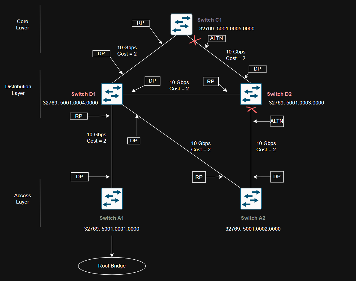
This campus network design and switch placement based of their Bridge ID is designed purposely to create a inefficent spanning-tree strcutre to show how improper spanning-tree archtecture can cause issues for traffic.
Network diagram shows Access layer Switch A1 becomes root bridge based of lowest bridge ID (bridge priority and MAC address) as compare to all other switches in the diagram.
Inefficent Root Bridge placement can cause many issues but few that stands out the most.
Network traffic might have to take longer, less direct paths to reach the root bridge. This can slow things down and make the network less efficient.
Root bridge becomes slow and overloaded can cause slow spanning-tree convergence means a longer outage time.
Best Practice to Select Root Bridge
Design network with one switch as a primary root bridge and another switch as secondary root bridge to achieve high availabilty.
As a common practice, the primary root bridge and secondary root bridge should be placed near the center of the Layer 2 network. Distribution switches would make more sense to select as primary and secondary root bridge as most traffic is expected to pass through the distribution layer switches.
Configuring Root Bridge
A Catalyst switch can be configured to use one of the following formats for its STP bridge ID:
Traditional 802.1D bridge priority value (16 bits), followed by the unique switch MAC address for the VLAN.
The 802.1t extended system ID (4-bit priority multiplier, plus a 12-bit VLAN ID), forllowing by a nonunique switch MAC address for the VLAN.
To see if switch already using the 802.1t extended system ID method, it can be varified from switches running-configuration:
1
Switch#show running-config | include spanning-tree extend system-id
You can also check the output of show spanning-tree command to see which method is used.
If the priority value is shown in the output will be multiple of 4096 plus the VLAN ID, STP is using Extended System ID method.
If the priority value displays the exact multiple of 4096. The VLAN ID is not added to the priority field. This means STP is using the Traditional 802.1D method.
To enable extended system ID method, following command can be used on the global configuration level:
1
Switch(config)#spanning-tree extend system-id
Root bridge can be configured using two methods:
Manual STP Root Bridge Configuration
Bridge prioroty can be set manually by giving lower-than-default bridge ID value to win a root bridge election. Important to note - you must know the bridge priorities of all other swithhes in the same VLAN so that you can choose a value that is less than all the others.
The commad to manually maniuplate the bridge priority as follows?
1
Switch(config)#spanning-tree vlan *vlan-list* priority *bridge-priority*
Key points about STP Bridge priority value
- The default STP bridge priority is 32,768.
- It can be set anywhere from 0 to 65,535 - lower is better.
- If extended system ID is used, the bridge priority becomes 32,768 + VLAN ID.
- In that mode, you can only set priorities in steps of 4096, from 0 to 61,440. reserving 4096 for the VLANs.
In the instance of multiple VLAN on switch, an appropriate VLAN needs to be set for each VLAN. Following command can be used to set the bridge priority for VLANs 5, 100, 200 to 4096.
1
Switch(config)#spanning-tree vlan 5,100,200 priority 4096
Even if you’re not sure on your priority value if it will be accepted, enter it anyways. The switch will respond (at least cisco catalyst switch) with list of accepted values that are multiples of 4096:
1
2
3
4
5
6
7
8
9
10
Switch-A1(config)#spanning-tree vlan 1,100,200 priority 4000
% Bridge Priority must be in increments of 4096.
% Allowed values are:
  0     4096  8192  12288 16384 20480 24576 28672
  32768 36864 40960 45056 49152 53248 57344 61440
Switch-A1(config)#spanning-tree vlan 5,100,200 priority 4000
% Bridge Priority must be in increments of 4096.
% Allowed values are:
  0     4096  8192  12288 16384 20480 24576 28672
  32768 36864 40960 45056 49152 53248 57344 61440
To validate, VLAN 5’s bridge ID has not changed means a specific value on the increment of 4096 needs to be entered.
1
2
3
4
5
6
7
Switch-A1(config)#do show spanning-tree bridge

                                                   Hello  Max  Fwd
Vlan                         Bridge ID              Time  Age  Dly  Protocol
---------------- --------------------------------- -----  ---  ---  --------
VLAN0001         32769 (32768,   1) 5001.0001.0000    2    20   15  ieee
VLAN0005         32773 (32768,   5) 5001.0001.0000    2    20   15  ieee
Statically setting up the VLAN 5’s priority to 4096 (Priority 4096 sys-id-ext 5) changes the VLAN 5 to become the root bridge.
1
2
3
4
5
6
7
8
9
10
11
12
13
14
15
16
17
18
19
20
21
!
Switch-A1(config)#spanning-tree vlan 5 priority 4096
!
!
Switch-A1(config)#do show spanning-tree vlan 5

VLAN0005
  Spanning tree enabled protocol ieee
  Root ID    Priority    4101
             Address     5001.0001.0000
             This bridge is the root
             Hello Time   2 sec  Max Age 20 sec  Forward Delay 15 sec

  Bridge ID  Priority    4101   (priority 4096 sys-id-ext 5)
             Address     5001.0001.0000
             Hello Time   2 sec  Max Age 20 sec  Forward Delay 15 sec
             Aging Time  300 sec

Interface           Role Sts Cost      Prio.Nbr Type
------------------- ---- --- --------- -------- --------------------------------
Gi1/3               Desg FWD 4         128.8    P2p
Auto-Configuration of STP Root Bridge
Using the root command makes the switch automatically choose a good STP priority, based on what it thinks other switches are using. You don’t have to set the exact number yourself.
1
2
3
4
5
6
7
8
9
10
11
12
13
14
15
16
17
18
19
20
21
22
23
24
25
26
27
28
29
30
31
32
33
34
35
36
37
38
39
40
41
42
43
44
45
46
47
48
49
!
Switch-A1(config)#do show spanning-tree vlan 1

VLAN0001
  Spanning tree enabled protocol ieee
  Root ID    Priority    32769
             Address     5001.0001.0000
             This bridge is the root
             Hello Time   2 sec  Max Age 20 sec  Forward Delay 15 sec

  Bridge ID  Priority    32769  (priority 32768 sys-id-ext 1)
             Address     5001.0001.0000
             Hello Time   2 sec  Max Age 20 sec  Forward Delay 15 sec
             Aging Time  300 sec

Interface           Role Sts Cost      Prio.Nbr Type
------------------- ---- --- --------- -------- --------------------------------
Gi0/0               Desg FWD 4         128.1    P2p
Gi0/1               Desg FWD 4         128.2    P2p
Gi0/2               Desg FWD 4         128.3    P2p
Gi0/3               Desg FWD 4         128.4    P2p
Gi1/0               Desg FWD 4         128.5    P2p
Gi1/1               Desg FWD 4         128.6    P2p
Gi1/2               Desg FWD 4         128.7    P2p
!
Switch-A1(config)#spanning-tree vlan 1 root primary
!
Switch-A1(config)#do show spanning-tree vlan 1
VLAN0001
  Spanning tree enabled protocol ieee
  Root ID    Priority    24577
             Address     5001.0001.0000
             This bridge is the root
             Hello Time   2 sec  Max Age 20 sec  Forward Delay 15 sec

  Bridge ID  Priority    24577  (priority 24576 sys-id-ext 1)
             Address     5001.0001.0000
             Hello Time   2 sec  Max Age 20 sec  Forward Delay 15 sec
             Aging Time  300 sec

Interface           Role Sts Cost      Prio.Nbr Type
------------------- ---- --- --------- -------- --------------------------------
Gi0/0               Desg FWD 4         128.1    P2p
Gi0/1               Desg FWD 4         128.2    P2p
Gi0/2               Desg FWD 4         128.3    P2p
Gi0/3               Desg FWD 4         128.4    P2p
Gi1/0               Desg FWD 4         128.5    P2p
Gi1/1               Desg FWD 4         128.6    P2p
Gi1/2               Desg FWD 4         128.7    P2p
To configure a VLAN as secondary root bridge.
1
2
3
4
5
6
7
8
9
10
11
12
13
14
15
16
17
18
19
20
21
22
23
24
25
26
27
28
29
30
31
32
33
34
35
36
37
38
39
Switch-A1(config)#do show spanning-tree vlan 200

VLAN0200
  Spanning tree enabled protocol ieee
  Root ID    Priority    32968
             Address     5001.0001.0000
             This bridge is the root
             Hello Time   2 sec  Max Age 20 sec  Forward Delay 15 sec

  Bridge ID  Priority    32968  (priority 32768 sys-id-ext 200)
             Address     5001.0001.0000
             Hello Time   2 sec  Max Age 20 sec  Forward Delay 15 sec
             Aging Time  300 sec

Interface           Role Sts Cost      Prio.Nbr Type
------------------- ---- --- --------- -------- --------------------------------
Gi1/2               Desg FWD 4         128.7    P2p
!
!
Switch-A1(config)#spanning-tree vlan 200 root secondary
!
!
Switch-A1(config)#do show spanning-tree vlan 200

VLAN0200
  Spanning tree enabled protocol ieee
  Root ID    Priority    28872
             Address     5001.0001.0000
             This bridge is the root
             Hello Time   2 sec  Max Age 20 sec  Forward Delay 15 sec

  Bridge ID  Priority    28872  (priority 28672 sys-id-ext 200)
             Address     5001.0001.0000
             Hello Time   2 sec  Max Age 20 sec  Forward Delay 15 sec
             Aging Time  300 sec

Interface           Role Sts Cost      Prio.Nbr Type
------------------- ---- --- --------- -------- --------------------------------
Gi1/2               Desg FWD 4         128.7    P2p
Here is what means by syntex “primary, secondary and diameter (haven’t used in this lab yet)
- Primary = makes this switch the preferred root
- Secondary = makes it the backup root
- diameter (optional) = helps STP adjust timers if the network is large