Breaking the Loop: Understanding Spanning Tree Protocol
Breaking the Loop: Understanding Spanning Tree Protocol
What is Spanning Tree Protocol?
Spanning Tree Protocol (STP) is a Layer 2 link-management (IEEE 802.1D bridge) protocol, provides path redundancy while preventing undesirable loops in the network.
Historical Context
The Spanning Tree Protocol (STP) was first standardized by the IEEE as part of 802.1D in 1990. Over time, it was improved and eventually replaced by the Rapid Spanning Tree Protocol (RSTP). RSTP was initially released as 802.1w and integrated into the main 802.1D standard in 2004. Spanning tree protocol is an algorithm that was invented by Radia Perlman.
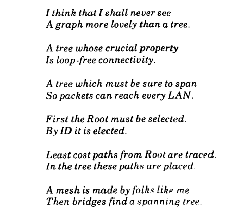
Radia Perlman published an article An algorithm for distributed computation of a spanning tree in an extended LAN by Radia Perlman in 1985. In the article, Radia Perlman beautifully described the STP in an artistic way.
Why We Need Spanning Tree Protocol?
In simple terms, one link is good but two links are better - that’s just an enough justficication to have STP.
TTL (Time to live), have you heard about it? Well, ethernet frames have not. Ethernet Frames does not use ttl value in ethernet frames as compare to IP Packet. In an IP Packet, TTL prevents packets to circulate indefinatily due to routing loops. Every time a router process an IP packet it reduce the TTL value by 1, means packet can only roam arround until TTL value reaches to 0.
Whereas ethernet frames does not use the TTL mechanisum, thus a need of Spanning Tree arise.
LANs are often designed with redundant links between switches i.e. access layer to distribution layer to enhance network resilience. However, these redundant paths can create loops, leading to broadcast storms and degraded performance.
STP dynamically identifies and disables redundant paths, allowing only one active path at a time. If the active path fails, STP reactivates a backup path, maintaining connectivity and fault tolerance.
What Spanning Three Does?
- STP computes a tree structure that spans all switches in a subnet or network.
- Redundant paths are placed in Blocking or Standby state to prevent frame forwarding.
- If forwarding port fails or becomes disconnected, the spanning-tree algorithm recomputes the spanning-tree topology so that the appropriate blocked links can be reactivated.
Common problems that STP prevents in a local area network:
- Broadcast storm: - If you remember LAN switch - a broadcast frame, multicast frame, or unknown unicast frame loops around a LAN indefinitely becouse of a loop in network.
- MAC table instability: - Switch puts an entry of learnt MAC address in its table and starts a counter of 300 seconds (by default value) and removes MAC address entry if no other frame arrives from the same source. However, a loop in network floods frames and makes mac address table instable since it can’t keep up the with the number of same frames arriving from different source addresses.
- Multiple frame transmission: - In a looped network, a unicast frame destined for host C will be received multiple times leading host C to confuse.
How Spanning-Tree Protocol Works?
STP/RSTP algorithm does create a spanning tree that ensures there is only one active path between switches for sending frames.
- Selecting which switch ports should forward frames (active path).
- Blocking the redundant paths to prevent loops.
In short, STP/RSTP ensures that data travels along one loop-free path, while other paths are blocked but can be activated if the primary path fails.
STP/RSTP has three mechanism whether to put an interface in a forwarding state:
Root switch is elected, all working interfaces on the root switch in a forwarding state.
Root cost, each nonroot switch has a cost to reach to the root switch, interfaces in spanning tree topology has cost based of interfaces speed. The switch port that has lowest cost path is called root port (RP).
Switches has dual physical link to other switches, link with lowest root cost becomes the designated switch and it’s port connected to the link is the designated port (DP) on the link.
Core Mechanisms
STP mechanism works by creating single, logical, loop-free topology across all connected switches. It’s a three step process of election and port designation, using special messages called Bridge Protocol Data Units (BPDUs).
- Election for Root Bridge
- Election for Root Ports
- Election for Designated Ports
Spanning-Tree Communication: Bridge Protocol Data Units (BPDUs)
STP operation happens when switches communicate with each other. Data messages are exchanged in the form of bridge protocol data units (BPDUs). A switch sends out BPDU frame out a port, using the unique MAC address of the port itself as a source address. The switch is unaware of the other switches around it, so BPDU frames are sent with destination address of the well-known STP multicast address 01:80:c2:00:00:00.
There are two types of BPDUs:
- Configuration BPDU, used for spanning-tree computation.
- Topology Change Notification (TCN) BPDU, used to announce changes in the network topology.
| Field Description | Number of Bytes |
|---|---|
| Protocol ID (always 0) | 2 |
| Version | 1 |
| Message Type (Configuration or TCN BPDU) | 1 |
| Flags | 1 |
| Root Bride ID | 8 |
| Sender Bridge ID | 8 |
| Port ID | 2 |
| Message age (in 256ths of a second) | 2 |
| Maximum age (in 256ths of a second) | 2 |
| Hello time (in 256ths of a second) | 2 |
| Forward delays (in 256ths of a second) | 2 |
Notice several key fields in the BPDU are related to bridge (switch) identification, path costs, and the timer values. These all work together so that the network of switches can converge on a common spanning-tree topology and select the same reference points within the network.
Electing a Root Bridge
A common framework is required for all network switches to agree on a loop-free topology. The reference point is called the root bridge. The term bridge was used even before STP was developed, if you see bridge, think switch.
Each switch has a unique bridge ID that identifies it to other switches. The bridge ID is 8-byte value consisting of the following fields:
- Bridge Priority (2 bytes): The Priority field can have a value of 0 to 65,535 and defaults to 32,768 (or 0x8000) on every Catalyst switch.
- MAC Address (6 bytes): A mac address address that is hard-coded and unique, can’t be changed. The MAC address used by a switch can come from the Supervisor module, the backplane, or a pool of 1024 addresses that are assigned to every supervisor or backplane, depending on the switch model.
Second part of bridge ID is MAC address, since switchports has their own MAC addresses. MAC addresses referred in the Bridge ID is often the switch’s base ethernet address.
Following switch output is from a physical switch, emulated switch operating systems does not have base ethernet address. Bridge ID uses the base ethernet MAC address.
1
2
physicalswitch#show version | i Base ethernet
Base ethernet MAC Address       : 00:6C:BC:5C:BD:80
To further explain the topic, Bride priority can be different based of VLAN number, for example, in the following physical switch output from show spanning-tree bridge command it list the Bridge ID’s for each VLAN but only uses the same MAC address on all VLANs since there is only one Base MAC address on a particular switch.
physicalswitch#show spanning-tree bridge

                                                   Hello  Max  Fwd
Vlan                         Bridge ID              Time  Age  Dly  Protocol
---------------- --------------------------------- -----  ---  ---  --------
VLAN0001         32769 (32768,   1) 006c.bc5c.bd80    2    20   15  rstp
VLAN0099         32867 (32768,  99) 006c.bc5c.bd80    2    20   15  rstp
VLAN0100         32868 (32768, 100) 006c.bc5c.bd80    2    20   15  rstp
VLAN0105         32873 (32768, 105) 006c.bc5c.bd80    2    20   15  rstp
VLAN0110         32878 (32768, 110) 006c.bc5c.bd80    2    20   15  rstp
Output shows VLAN 1 has bridge priority of 32768 + VLAN number of 1, bridge id becomes 32769 whereas VLAN 99 shows the bridge priority of 32768 + VLAN number of 99, bridge id becomes 32867.
The election of a root bridge, Switches boots, assumes itself as a root bridge but as soon as other switches are powered on election process of a root bridge starts by sending out BPDUs with a root bridge ID equal to its own bridge ID and a senders bridge ID that it its owns bridge ID.
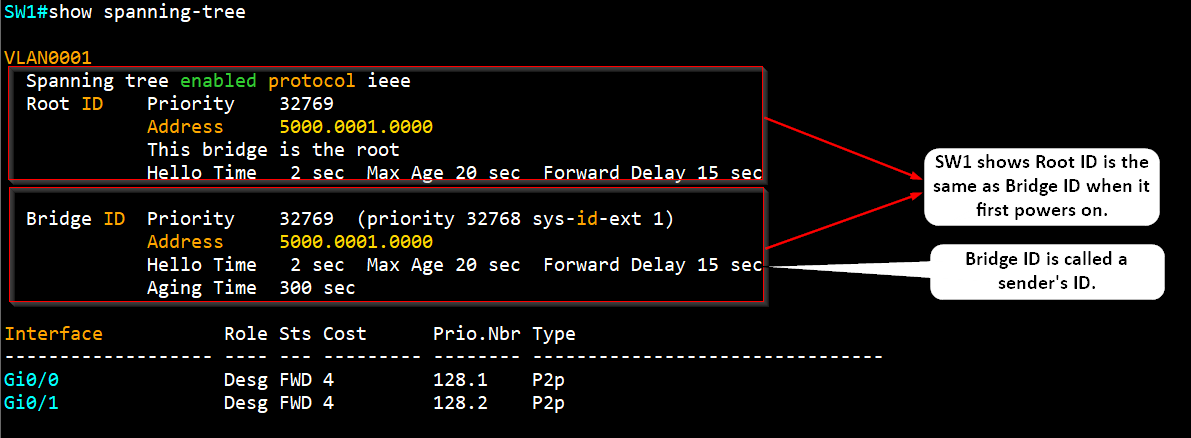
Senders bridge ID (local switch’s bridge ID) simply tells other switches who is the actual sender of the BPDU message. After a root bridge is decided on, configuration BPDUs are sent only by the root bridge. All other bridges must forward or relay the BPDUs, adding their own sender bridge IDs to the message.
BPDU’s messages are analyzed to see if a “better” root bridge is being announced. A root bridge is considered better if the root bridge ID value is lower than another. If two bridge priority values are equal, the lower MAC address makes the bridge ID better.
The root bridge election converges and all switches agree one of them is the root bridge. However, if a new switch is connected to the network with lower bridge ID or bridge ID is equal to current switches but the mac address is lower, all the switches will reconsider and elects the new switch as root bridge.
Root bridge election is an ongoing process, triggered by root bridge ID changes in the BPDUs every 2 seconds (by default).
Electing Root Ports
Once the Root Bridge is elected, every other switch (Non-Root Switch) must select a single Root Port (RP). The RP is the port that offers the best path back to the Root Bridge and is always put into the Forwarding state.
The “best path” is determined by comparing costs:
Root Path Cost: This is the cumulative cost to reach the Root Bridge. This value is carried inside the BPDU messages and is updated by each switch along the path.
Path Cost: This is the local cost of a specific link or port (e.g., Fast Ethernet link cost is 19). This value is NOT in the BPDU. The receiving switch adds its incoming port’s local Path Cost to the received Root Path Cost to calculate its new total cost.
The original IEEE 802.1D formula is:
\[\text{Original STP Cost} = \frac{1000 \text{ Mbps}}{\text{Link Bandwidth (in Mbps)}}\]For links that are 10Gbps and more are rounded down to 1 (same as 1Gbps)
STP Port Cost Table
| Link Bandwidth | Old STP Cost (802.1D) | New STP Cost (IEEE) |
|---|---|---|
| 4 Mbps | 250 | 250 |
| 10 Mbps | 100 | 100 |
| 16 Mbps | 63 | 62 |
| 45 Mbps | 22 | 39 |
| 100 Mbps (Fast Ethernet) | 10 | 19 |
| 155 Mbps | 6 | 14 |
| 622 Mbps | 2 | 6 |
| 1 Gbps (Gigabit Ethernet) | 1 | 4 |
| 10 Gbps | 0 | 2 |
Electing Designated Ports
To remove the possibility of bridging loops, STP makes a final computation to identify one designated port on each network switch. Switches choose a designated port based on the lowest cumulative root path cost to the root bridge.
For example, a switch always has an idea of it’s own root path cost, which it announces in its own BPDUs. If a neighboring switch on a shared LAN segment sends a BPDU announcing a lower root path cost, the neighbor must have the designated port. If a switch learns only of higher root path cost from other BPDUs received on a port, however, it then correctly assumes that its own receiving port is the designated port for the segment.
STP has a set of progressive states that each port must go through, regardless of the type or identification. These states actively prevents loops from forming and are described in the next section.
In each determination process discussed so far, two or more links might have identical root path costs. This results in a tie condition, unless other factors are considered. Al tie breaker STP decisions are based on the following sequence of four conditions:
- Lowest root bridge ID
- Lowest root path cost to the root bridge.
- Lowest sender bridge ID
- Lowest sender port ID
Explanation of Election process of Root bridge, root port and designated port.
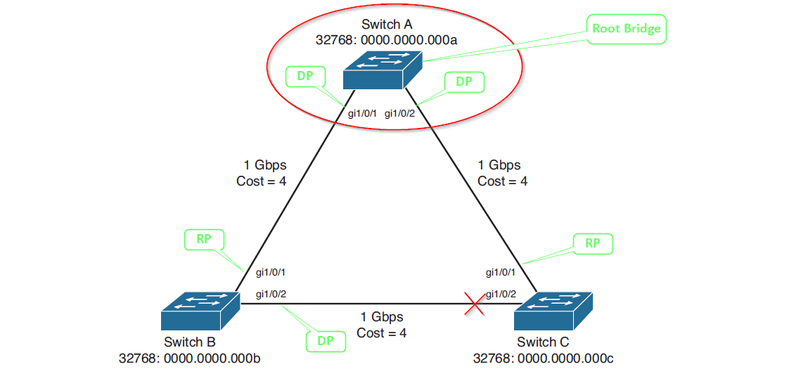
Switch A (Root Bridge) When Switch A communicates with Switch B, it sends BPDUs out gi1/0/1 advertising a root path cost of 0. Switch B responds with BPDUs advertising a root path cost of 4. Since Switch A has the lower root path cost, gi1/0/1 becomes a designated port. All ports on the root bridge are designated ports by definition.
When Switch A communicates with Switch C, it sends BPDUs out gi1/0/2 advertising a root path cost of 0. Switch C responds with BPDUs advertising a root path cost of 4. Switch A gi1/0/2 becomes a designated port due to its superior root path cost of 0.
Switch B When Switch B communicates with Switch A, it receives BPDUs advertising a root path cost of 0 on gi1/0/1. Switch B calculates its own root path cost as 4 by adding the incoming link cost. Since Switch A offers the best path to the root bridge, Switch B gi1/0/1 becomes the root port.
When Switch B communicates with Switch C across the B-C link, both switches advertise a root path cost of 8 on their respective gi1/0/2 ports. With equal root path costs, the tiebreaker becomes the bridge ID comparison. Switch B has the lower bridge ID (32768:0000.0000.000b), so its gi1/0/2 port becomes the designated port for this connection.
Switch C When Switch C communicates with Switch A, it receives BPDUs advertising a root path cost of 0 on gi1/0/1. Switch C calculates its own root path cost as 4 by adding the incoming link cost. Since Switch A offers the best path to the root bridge, Switch C gi1/0/1 becomes the root port.
When Switch C communicates with Switch B across the B-C link, both switches advertise a root path cost of 8. However, Switch C has the higher bridge ID (32768:0000.0000.000c), causing it to lose the designated port election. Switch C gi1/0/2 becomes neither a root port nor a designated port, forcing it into the blocking state to prevent loops.
STP States
For a switch port to participate in STP and eventually forward traffic, it must pass through a set of sequential states, designed to prevent network loops.
- Disabled
- Role: Administrative shutdown.
- Action: The port is shut down by a network administrator or a system fault. This state is outside the normal STP progression.
- Blocking:
- Role: Loop prevention and startup.
- Action: The initial state for any port to prevent loops. The port only receives BPDUs to hear about the topology. It cannot send/receive data or learn MAC addresses. Ports designated as redundant links (Alternate/Backup) also remain in this state.
- Listening:
- Role: Determining port status.
- Action: The port is transitioning toward the active state. It sends and receives BPDUs to actively participate in the STP election process (determining if it should be a Root Port or Designated Port). It cannot send/receive data or learn MACs. If the port loses the election, it reverts to the Blocking state.
- Learning:
- Role: Preparing to forward.
- Action: After a Forward Delay Timer (default 15 seconds) in the Listening state, the port enters Learning. It starts learning MAC addresses (adding them to the MAC table) but still cannot send/receive data frames. This prepares the switch to efficiently forward traffic immediately upon activation.
- Forwarding:
- Role: Active participation.
- Action: After a second Forward Delay Timer (default 15 seconds) in the Learning state, the port enters the operational state. It is now a fully functioning port: it sends/receives data frames, learns MAC addresses, and continues processing BPDUs. Only Root Ports and Designated Ports reach this state.
STP Timers
STP uses three primary timers to manage the topology changes, ensuring the network has time to stabilize and prevent temporary loops during port state transitions.
| Timer | Default Value | Purpose |
|---|---|---|
| Hello Time | 2 seconds | The interval at which the Root Bridge sends out Bridge Protocol Data Units (BPDUs). This is the heartbeat of the STP topology. |
| Forward Delay | 15 seconds | The time a port spends in both the Listening state and the Learning state (a total of 30 seconds to transition to Forwarding). This timer prevents temporary loops by delaying the start of data forwarding. |
| Max Age | 20 seconds | The maximum time a switch will store a superior BPDU without hearing a new one from the Root Bridge. If this time expires, the switch assumes the Root Bridge has failed or the link to it is down and initiates a new STP election. |
Topology Changes
A Topology Change (TCN) occurs when the STP structure is modified, typically due to a link failure or a new link becoming active. This forces the switches to rapidly age out their MAC address tables to prevent forwarding data to obsolete destinations.
Indirect Topology Changes
An indirect topology change is an event that affects connectivity to the Root Bridge but is not detected directly by the root.
- Example: A non-root switch (SW2) loses its Root Port link to another non-root switch (SW3). SW2 must now find a new path to the Root Bridge.
- Result: The Max Age timer expires, forcing the switch to assume the Root Bridge is gone and initiate a full recalculation. This process takes 50 seconds (Max Age + 2x Forward Delay) in traditional STP, leading to significant convergence delay.
Insignificant Topology Changes
This refers to events that do not impact the active forwarding path of the spanning tree and therefore do not trigger a fast convergence mechanism.
- Example: A port that was already in the Blocking state goes down. Since it wasn’t forwarding traffic, its failure doesn’t change the active path or cause a loop.
- Result: These changes are often ignored by the main TCN process, though local updates may still occur.
Types of STP
There are several evolutions of STP, mainly differing in how they handle multiple VLANs and how quickly they converge.
Common Spanning Tree (CST)
- Protocol: Defined by the original IEEE 802.1D standard.
- Function: Creates a single spanning tree instance for the entire network, regardless of how many VLANs exist.
- Drawback: It treats all VLANs as a single broadcast domain for STP purposes. This means all VLANs follow the same single forwarding path, wasting bandwidth on redundant links. Convergence is slow (50 seconds).
Per-VLAN Spanning Tree (PVST)
- Protocol: Cisco proprietary enhancement.
- Function: Runs a separate, independent STP instance for every VLAN.
- Advantage: Allows for load balancing. You can configure VLAN 10 to forward traffic over one link and VLAN 20 to forward traffic over a different link (by manipulating the Root Bridge priority for each VLAN), utilizing all available links and improving resource usage.
Per-VLAN Spanning Tree Plus (PVST+)
- Protocol: Cisco proprietary enhancement that builds upon PVST.
- Function: Provides the same per-VLAN STP functionality as PVST but adds interoperability with standard 802.1Q trunking and the non-Cisco CST protocol.
- Current Status: PVST+ is the most common STP variant used in mixed-vendor Cisco environments today, as it ensures proper functioning when connected to switches running the original CST.
Rapid Spanning Tree Protocol (RSTP / 802.1w)
- Note: Although not listed, it’s the modern successor. It significantly improves convergence time (often less than 1 second) by replacing the timers with a faster handshake process for port role negotiation.
STP Convergence Process
The Convergence Process in traditional Spanning Tree Protocol (STP) is the sequence of events and timers required for all switches in a network to agree on a single, loop-free topology (the spanning tree) after a change occurs.
The entire process takes approximately 50 seconds (in traditional 802.1D STP) when a forwarding path fails.
Failure Detection (Max Age Timer)
This phase detects the loss of the active link or Root Bridge.
- Action: When a switch loses its Root Port (RP) link or stops receiving BPDUs from its designated neighbor.
- Timer: The switch waits for the Max Age Timer (default 20 seconds) to expire. This period prevents instability from temporary BPDU loss.
- Result: If the timer expires, the switch assumes the current root information is invalid and initiates a new STP election.
Port Re-Election and Delay (Forward Delay Timer)
This phase establishes the new Root Port (RP) and Designated Ports (DPs) and prepares them to forward traffic safely.
- Listening State: The ports start sending and receiving BPDUs to negotiate their new roles (RP or DP). The port stays here for the Forward Delay Timer (default 15 seconds).
- Learning State: After the first 15 seconds, the port moves to the Learning state. It starts populating its MAC address table to ensure efficient forwarding when active. The port stays here for a second Forward Delay Timer (default 15 seconds).
Activation and Stability
- Forwarding State: After the second 15-second delay (a total of 30 seconds spent in Listening and Learning), the new Root Port or Designated Port transitions to the Forwarding state, and the network topology has successfully converged.
| Phase | State | Timer Value | Key Action |
|---|---|---|---|
| Detection | Blocking | Max Age (20s) | Detect failure of the current active path. |
| Delay 1 | Listening | Forward Delay (15s) | Elect new port roles (RP/DP). |
| Delay 2 | Learning | Forward Delay (15s) | Populate MAC address table. |
| Activation | Forwarding | 0s | Begin passing traffic on the new path. |
Note: Modern protocols like Rapid STP (RSTP) eliminate the 50-second delay by using a synchronization and handshake mechanism, allowing for near-instantaneous convergence (often under 1 second).
References
- Study guide by David Hucaby CCNP Routing and Switching SWITCH 300-115 Official Cert Guide
- Study gudie by Wendell Odom, David Hucaby, Jason Gooley CCNA 200-301 Official Cert Guide Library, 2nd Edition
- Article by Radia Perlman, An algorithm for distributed computation of a spanning tree in an extended LAN
- Cisco whitepaper Understand Rapid Spanning Tree Protocol (802.1w)